Hydraulic Industrial Corporation of America
 Continuous Flow • Zero Leakage • Industrial-Duty Reliability
HICORP Transfer Valves are engineered for critical applications where uninterrupted flow and absolute sealing integrity are required. Designed for duplex filtration systems and demanding industrial processes, these valves allow smooth transfer between flow paths without shutdown, pressure loss, or leakage.
Unlike traditional O-ring designs, HICORP valves utilize a positive mechanical shoe-seal system that retracts during changeover to eliminate friction and wear—then locks securely into place to provide true “No-Leak” shutoff.
Key Advantages
- Zero-Leak Shutoff
Positive mechanical shoe seals provide tight isolation without O-rings or spectacle blinds. - Continuous Flow Operation
Change flow paths without interrupting system operation or depressurizing the line. - Low Torque, Low Wear Design
Retractable elastomer seals eliminate friction during transfer, extending seal life. - Low Pressure Drop
Optimized internal flow paths improve efficiency and system performance. - API 614 Compliant
Suitable for critical oil & gas and process industry applications.
Valve Configurations
HICORP Transfer Valves are available in multiple configurations to match your piping layout:
- 6-Way Same-Side Continuous Flow
- 6-Way Opposite-Side Continuous Flow
- 6-Way Inline Continuous Flow
- 6-Way Split Transfer
- 3-Way Continuous Flow
Sizes: 1½″ through 8″
Pressure Classes: ANSI Class 150 & 300
Connections: Flanged, Butt-Weld, or Threaded
Construction & Materials
- Carbon steel body (standard)
- Optional 304 or 316 stainless steel construction
- Stainless steel operating shaft and internal mechanism
- Soft-seat elastomer seals available in Buna, Viton®, or Neoprene
- Designed for pressures up to 675 PSI
Standard Specifications
| Parameter | Details |
|---|---|
| Valve Sizes | 1½” through 8″ |
| Body Materials | Carbon steel (standard) or 304L/316L stainless steel |
| Seals | Buna-N (250°F max), Viton (350°F max), Neoprene (250°F max) |
| Temperature Range | –20°F to maximum seal rating |
| Pressure Ratings (Carbon Steel @ 200°F) | 150# ANSI flanged: 260 psi 300# ANSI & buttweld: 675 psi Consult factory for stainless steel or higher ratings |
| Standard Differential Pressure | 50 psi (1½”–4″) |
| High Differential Pressure Option | Up to 100 psi (1½”–2″), 75 psi (3″–4″), 50 psi (6″–8″) |
| Connections | 150# or 300# ANSI flanges, butt-weld, male NPT, SAE flanges |
| Equalizing Line | Required for operation (ball, gate, globe, or none – customer piping option) |
Pressure Drop Performance Curves are available for 200 SUS and 2000 SUS fluids across all sizes (1½”–6″ shown in technical data). Low pressure drop is maintained even at high flows.
Dimensions (Approximate – inches)
6-Way Same-Side / Opposite-Side / Inline (Consult factory for exact configuration-specific drawings)
| Size | A | B | C | D | E* | F | G* | Weight (lbs) |
|---|---|---|---|---|---|---|---|---|
| 1½” (150/300#) | 6⅜” | 9⅜–10″ | 14⅞” | 20⅜” | 13¾” | 5″ | 5½” | 76–91 |
| 2″ (150/300#) | 6¾” | 10¼–12″ | 14⅞” | 20⅜” | 13¾” | 7″ | 6¼” | 99–114 |
| 3″ (150#) | 7¾” | 12–14″ | 17″ | 22¾” | 16¼” | 7″ | 6¾” | 161–176 |
| 3″ (300#) | 8½” | 12¾–14″ | 17¾” | 23½” | 17″ | 7–9″ | 6¾” | 200–215 |
| 4″ (150/300#) | 10¼” | 15⅝–21″ | 21⅞” | 28¾” | 21″ | 8⅜” | 7⅞” | 254–269 |
| 6″ (150#) | 11½” | 18⅜–26″ | 26⅛” | 32⅞” | 25¼” | 9⅞” | 10″ | 431–480 |
| 6″ (300#) | 13″ | 19⅜–26″ | 27⅝” | 34⅛” | 26¾” | 9⅞” | 10″ | 545 |
*Approximate dimensions; full detail drawings available per configuration (same-side, opposite-side, inline, split).
Ordering Nomenclature (Example)
TV6-CS-24-SS-F1-B-B-X###
- Model: TV6 (6-way), TV3 (3-way), TVS (split 6-way / twin-pack)
- Body: CS (carbon steel), S2 (304L SS), S4 (316L SS)
- Size: 24 (1½”), 32 (2″), 48 (3″), 64 (4″), 96 (6″), 128 (8″)
- Porting: SS (same-side std), OS (opposite-side std), IS (inline), XS (split), SH/OH/IH (high-diff options)
- Equalizing Valve: B (ball), G (gate), L (globe), N (none)
- Seals: B (Buna), V (Viton), N (Neoprene)
- Connection: F1 (150# flange), F3 (300# flange), BW (butt-weld), etc.
- Special Variation: X### (custom)
Twin-pack (dual 3-way) and high-differential-pressure variants are also available – consult factory for exact code.
Serviceability & Maintenance
All internal components—including seal assemblies, shoe kits, and internal stacks—are field replaceable, minimizing downtime and lifecycle cost. Replacement components are interchangeable with HYCOA JR-33 style valves, simplifying spare parts management.
Typical Applications
- Duplex basket and cartridge filtration systems
- Oil & gas processing
- Chemical and petrochemical plants
- Power generation facilities
- Industrial water and wastewater systems
- Any process requiring uninterrupted flow during changeover
Built for Critical Service
HICORP Transfer Valves deliver reliable, zero-leak performance in the most demanding environments—making them the trusted choice for engineers who cannot afford downtime.
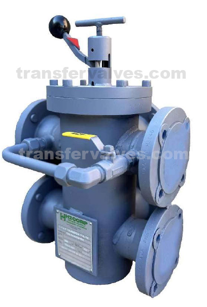
Operating Instructions (Quick Reference)
- Open equalizing/fill line valve and allow pressure to balance (larger vessels may require several minutes).
- Turn “T” handle counterclockwise ≈6–7 turns.
- Push ball handle down to unseat shoes.
- Rotate ball handle 180° (red arrow points to active ports).
- Release ball handle and hand-tighten “T” handle clockwise (20 in-lb max).
- Close equalizing valve.
Maintenance: Replacement shoe assemblies, seal kits, and internal stacks are readily available and fully interchangeable with existing systems.
These transfer valves set the industry standard for reliability in API 614 auxiliary lube oil skids, power plants, gas turbines, and heavy industrial applications. Custom configurations, materials, and testing are available to meet your exact requirements.
Contact Northeast Controls Incorporated for sizing assistance, drawings, pressure-drop curves, or a quotation. TEL: 201-419-6111 | FAX: 201-419-6109 | sales@nciweb.com | www.nciweb.com
All dimensions and ratings are for reference. Final selection should be confirmed with factory engineering.